Switches and Links

|
Label # |
Pins/switch |
Input/output type |
|---|---|---|
|
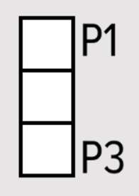
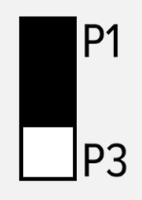
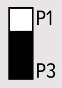
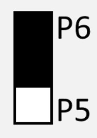
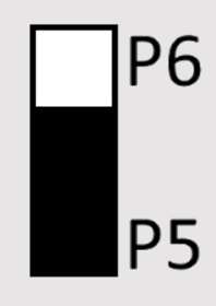
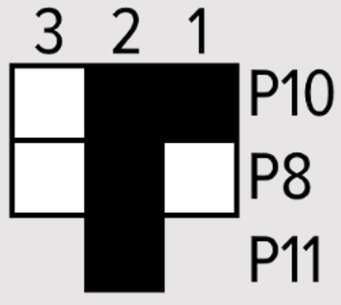
Selection links for Input 1 configuration |
||
|
A |
|
0V to 10V analog input |
|
|
0V to 10V digital input (default is HIGH) |
|
|
|
0mA to 20mA input |
|
|
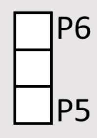
Selection links for Input 2 configuration |
||
|
B |
|
0V to 10V analog input |
|
|
0V to 10V digital input (default is HIGH) |
|
|
|
0mA to 20mA input |
|
|
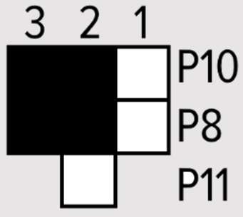
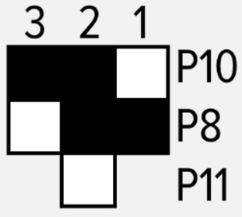
Selection links for output configuration |
||
|
C |
|
Relay output with NC |
|
|
Relay output with NO |
|
|
|
0V to 10V analog output |
|
|
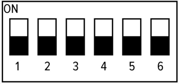
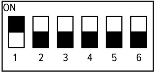
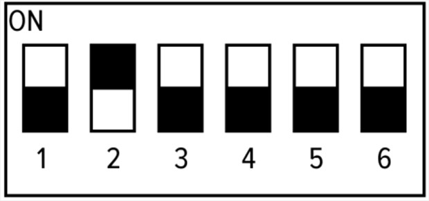
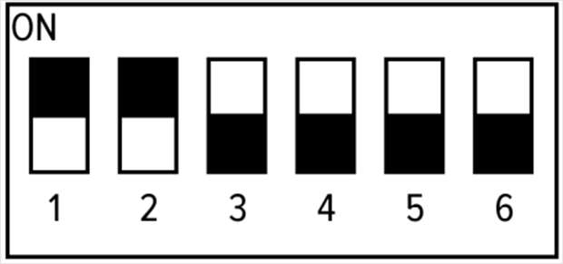
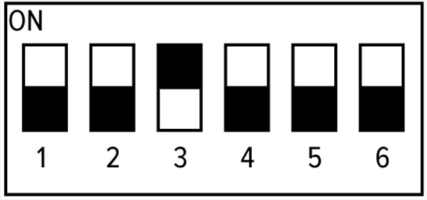
DIP switch P1 Switch 1 to Switch 4: set OSDP address on the bus Switch 5 to Switch 6: Unused |
||
|
D |
|
Device address 1 |
|
|
Device address 2 |
|
|
|
Device address 3 |
|
|
|
Device address 4 |
|
|
|
Device address 5 |
|
|
Enclosure lid tamper sensor P2 |
||
|
E |
Disable by placing a shorting plug on this 2-pin header. |
|