Mounting S1000 in 3000 Enclosure
Warning: Disconnect power from the system prior to installation or service.
Caution: Installation must comply in accordance with National Electrical Code (ANSI/NFPA70) or Canadian Electrical Code (as applicable) and must only be performed by personnel trained in intrinsically safe systems. Improper installation may result in serious injury or damage.
Before installing, read and understand these instructions completely.
Note: For additional product descriptions, specifications and installation, see the S1000 Controller Installation Guide.
The Retrofit back-plate allows an installer to upgrade a legacy Sonitrol 3000 series system to the current Sonitrol CORE product line without replacing the installed enclosure(s). The S1000, Remote IO and the expansion cards are supported on the Retrofit back-plate.
Note: The use of an existing 3000 series enclosure for a Sonitrol CORE UL listed installation is not allowed and has not been evaluated by UL.
The accessory kit includes the following hardware:
-
1 retrofit back-plate
-
1 battery cable 500mm
-
14 x 15mm standoffs male-female Hex - M3x15 + 6mm
-
6 x 25mm standoffs male-female Hex - M3x25 + 6mm
Configure the Back-Plate
-
Remove the existing panels. Cut the nylon standoffs close to the sheet metal using side-cutters.
-
Using the back-plate as a guide, position the back-plate into the enclosure as shown in the following illustration.

-
Mark the four holes as shown above.
-
Remove the backplate and drill four holes into the enclosure using a 1/8’ drill bit.
-
Mount the back-plate to the enclosure using four #8 self-tapping screws.
-
Optional Cellular expansion drill a 3/8’ hole through the top of the enclosure for the cellular antenna as shown in the Completed Enclosure illustration.
-
Install the included standoffs (15mm and 25mm) onto the back-plate as shown in the following illustration.

Mount the S1000 Controller
-
Install the tamper spring provided with the S1000 and the Remote IO as shown in the following illustration.


-
Install tamper jumpers on the S1000 or the Remote IO as they are not used with this enclosure.
-
Mount the S1000 or the Remote IO using four 3mm screws on each corner and two 9mm standoffs near the center of the board. The screws and standoffs are provided with the S1000 and the Remote IO.
-
Install up to three additional expansion cards onto the S1000 or the Remote IO using screws provided with each module.
Mount the Audio 8 module
-
Using screws and 9mm standoffs provided with the Audio 8, mount the Audio 8 using six 3mm screws at the outer edge of the Audio 8 and two 9mm standoffs near the center of the Audio 8.
-
When required, install the optional SE1-Audio8 onto the Audio 8 using two 3mm screws provided with SE1-Audio8.
-
When required, install an optional expansion board onto the expansion slot using two 3mm screws provided with the expansion module.
The following illustration shows the S1000 Controller and the Audio 8 PCBs mounted in the 3000 series enclosure with the retrofit back-plate.
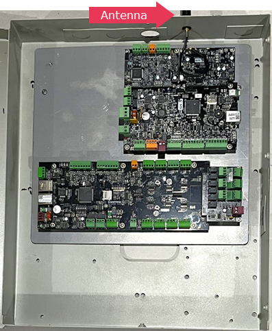
Completed Enclosure