UL Standards Compliance
The S1000 Controller must be fixed wired to a power source. For fixed wired power connections, a readily accessible all-pole disconnect device must be incorporated external to the equipment.
At the time of installing the S1000 Controller, separation of power limited and non-power limited circuits must be maintained by using individual conduits or by other similar means.
A minimum ¼ inch (6.4 mm) is provided between all Class 2 or 3 conductors and all electric light, power, Class 1 conductors, non-Class 2 or 3 signaling conductors, or medium-power network-powered broadband communications-circuit conductors.
-
Request to enter or exit requirements - A delay time of 60 seconds or less must be used to prevent an alarm from activating during entry or egress.
-
Alarm sounding device - Output used to connect alarm sounding device must be operated continuously for a minimum of 15 minutes after an alarm is activated.
User must manually bypass each faulted zone to bring awareness of the potential lapse in coverage for a particular area or zone. A force arming feature (such as auto-arm, auto-bypass) is not permissible.
-
When there is a loss of communication with the monitoring station in an armed state, the loss of communication event must be treated as an alarm. In a disarmed state, the loss of communication event must be treated as a trouble.
The S1000 Controller was evaluated with the Sonitrol Virtual Receiver (UL File BP5025) using SIA DC-09 protocol.
-
An automation system unit must be completely duplicated and provision must be made for switchover in a period of not more than 90 seconds, without loss of signal during this time.
-
Each message sent between the premises control unit and the supervising station receiving equipment must be protected with a cryptographic authentication means.
Signaling is identified as either IP or cellular, or both.
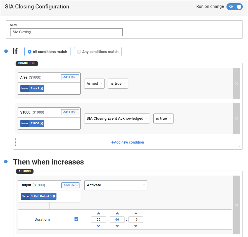
The S1000 Controller must be configured to provide an audible or visual indication, or both, when it receives an arming acknowledgment from the central station.
For example, a rule can be configured in Sonitrol CORE as shown:
Minimum 4 hours of power is provided by a minimum battery requirement is 12VDC at 7Ah. The maximum power the S1000 Controller can support is 12VDC at 17Ah.
The following listed features of the S1000 Controller and related peripherals are not mandatory requirements for UL 2610 and UL 294 and, therefore, are not evaluated by UL.
Some of the non-UL verified features of the S1000 Controller or related peripherals may be mandatory requirements of other regional certification standards and are verified by applicable certification entities.
|
Peripherals |
Model |
Details |
|---|---|---|
|
3D biometric reader |
Various models |
Optional third party devices |
|
Aperio devices |
Various models |
Optional third party devices |
|
Axis camera integration |
Various models |
Optional feature |
|
Battery temperature sensor |
Various models |
This is EN 50131 certified. |
|
Cellular antennas |
SE1-CELL-PCB-L |
Optional antenna models Note: Only the AGM410 cellular antenna model is currently approved for UL compliance. |
|
Cellular + WiFi expansion card |
SE1-CELL-PCB-L |
Optional feature GPS and GNSS using open public protocols. |
|
Display reader |
SD1-TKD-B SD1-TKD-B-PRX-B |
Optional feature Not within UL scope. |
|
Dual flash memory |
S1000-PCB |
Optional feature |
|
Elevator control configuration |
Various models |
Optional feature Elevator control is not within UL scope. |
|
Inovonics EchoStream devices |
Various models |
Optional third party devices |
|
IoT devices |
Various models |
Optional third party devices |
|
Mini camera |
SD1-MINICAM-PENC |
Optional feature |
|
Audio |
SD1-AUDIO4-PCB SE1-AUDIO-PCB SE1-AUDIO8-PCB |
Optional feature Not within UL scope. |
|
Modbus integration |
Various models |
Optional third party devices |
|
Power supply |
SP1-PSU - 5A |
This is EN 50131 certified. |
|
Pulse counter |
Various models |
Optional third party devices |
|
Relay output |
SD1-REMIO-PCB |
Optional feature 120AC, 0.5A relay output |
|
Relay output |
S1000-PCB |
Optional feature 120AC, 0.5A relay output |
|
Software configurable inputs |
Analog and digital |
Optional feature |
|
Third party alarm integration |
Various models |
Optional third party devices Note: The S1000 communication will be UL certified independently for third party alarm integration. |
|
Various sensors on the sensor remote device |
SD1-2ADI-PCB |
Temperature, humidity and motion sensors have no connection to UL applications. |
The following table provides a summary of firmware versions of peripheral devices supported by S1000.
|
Peripherals |
Firmware Version |
|---|---|
|
S1000 |
1.2.x |
|
SD1-2AD1 |
1.2.x |
|
SD1-AUDIO4 |
1.2.x |
|
SD1-AUDIO8 |
1.2.x |
|
SD1-CRI |
1.2.x |
|
SD1-REMIO |
1.2.x |
|
SE1-AUDIO |
1.2.x |
|
SE1-ETH |
1.2.x |
|
Keypad |
3.1.x |
CAN/ULC 60839-11-1:2022: N/A
|
Access control component |
Level |
|---|---|
|
Destructive attack |
I |
|
Endurance |
IV |
|
Line Security |
I |
|
Standby power |
I |
|
Circuit |
Maximum length (m) |
Wire gauge (AWG) |
Line resistance (Ω) |
|---|---|---|---|
|
Reader connector |
150 |
22 |
10 |
|
Alarm input and output |
250 |
22 |
15 |
|
AUDIO Sensor |
150 |
22 |
10 |
|
Audio bus |
304.8 |
22 |
16 |
|
Speaker out |
15 |
16 |
8 |
|
RS485 connections |
400 |
22 |
22 |
|
RS232 connections |
25 |
22 |
5 |
UL 2610: End of Line Resistors must be 10K, 1%, 0.25W supplied by Sonitrol. 18AWG, 6 inches long lead must be soldered to the EOL resistors and mechanically secured. Tubing (YDPU2) must cover all exposed leads. Control unit accessories, End of Line Resistors Model(s) number is EOLR-10K.
To maintain UL compliance when installing the S1000 Controller in an enclosure with a power supply, an AC surge suppressor must be included.
To install the AC surge suppressor supplied in the accessory kit bag:
The following illustration shows a surge supressor mounted on the base plate of the MENC enclosure along with a terminal block.
-
Mount the AC surge suppressor on the wall of the enclosure using the standoff to attach it to the wall with the supplied nut (as shown below).

- Connect the AC Mains supply input to the terminal block with fuse.
- Connect the cable marked INPUT from the AC surge suppressor to the terminal block with fuse.
- Connect the cable marked OUTPUT from the AC surge suppressor to a UL recognized IEC Connector.
-
Connect the IEC Connector to the IEC socket on the S1-PSU-2A power supply.

Schematic diagram of how to connect the surge protection device for the power supply unit.
 Tip: If fused terminal block is used, the fuse rating must be 3.15A 5x20mm. The recommended fuse part numbers are Schurter 0034.3122 and Littlefuse 02183.15MXP
To maintain UL compliance when wiring the S1000 Controller, TVS diodes (supplied in the accessories kit bag) must be connected to earth for the following:
- TVS SA18CA-E3/54: On S1000 connect this TVS between V+ on PL3 (O/C outputs) to earth on PL4, and V- on PL3 to earth on PL4.
- TVS SA15CA-E3/54: On S1000 connect this TVS between V+ on PL6 (RS485 serial port) to earth on PL4, and V- on PL6 (RS485 serial port) to Earth on PL4, when connecting to a keypad reader.
- TVS SA15CA-E3/54: On SD1-AUDIO4-PCB connect this TVS between 485+ on PL3 (RS485 serial port) to earth on PL3, and 485- on PL3 (RS485 serial port) to earth on PL3 when connecting to a keypad reader.
Connect the provided grounding wire to the grounding nodes on the base and the lid of the enclosure. The following illustrations show the grounding nodes connection in the MENC and MENCS enclosures.
|
Specifics for the MENC
|
Specifics for the MENCS
|

